Assembling G-TAP A Series 2
IMPORTANT: Always use an ESD -preventive wrist or ankle strap and ensure that it makes good skin contact when installing or removing tap and its Fan, battery and adapter. The strap can be connected to one of the following:
|
■
|
ESD wrist strap connector. |
|
■
|
Any unpainted surface on the chassis. |
Installing and Removing a Fan Tray
The G-TAP A Series 2 is shipped with its fan tray installed. The fan tray is field-replaceable in case one of the fan fails. During normal operation, to stop the fan use GigaVUE‑FM or GigaVUE-OS CLI rather than fan tray removal. Follow the below steps to install or remove a fan tray :
|
1.
|
Place the tap upright on a flat surface or on rack. |
|
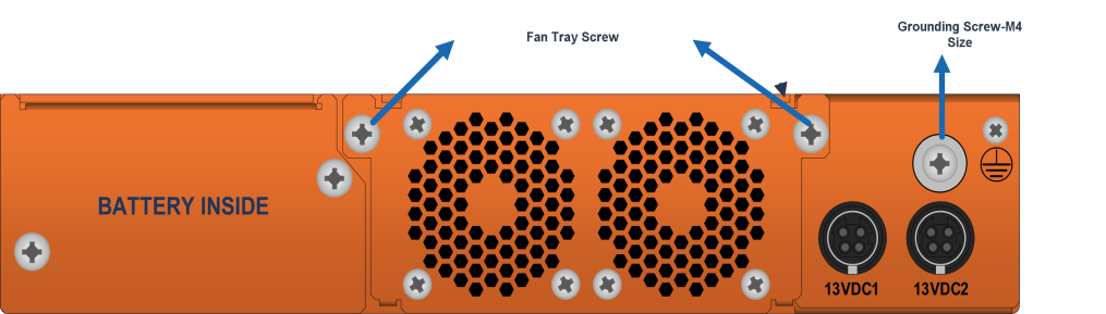
Figure 1
|
G-TAP A-TX21 Rear Chassis |
|
2.
|
Loosen the screws on the fan tray . |
|
3.
|
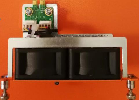
Gently pull the fan tray out. |
|
4.
|
Insert the new fan tray in to the chassis with care. |
|
5.
|
Tighten the screws .If the fan was stopped by command before fan replacement, please restart fan after tightening the screw. |
Note: Fan tray replacement must be done in two minutes to avoid running the system from over temperature or heating.
Rack-Mounting G-TAP A Series 2
This section describes how to rack-mount the G-TAP A Series 2 chassis in a standard 1RU rack space using the hardware provided with the chassis. You can install the G-TAP A Series 2 two-post racks with a minimum depth of 7 inches.
Safety Precautions
Before you get started rack-mounting the G-TAP A Series 2, make sure you have read the following safety precautions:
|
1.
|
There are a wide variety of racks available on the market. |
|
2.
|
Consult your rack vendor for mounting instructions before installing theG-TAP A-TX21. Ensure you install any stabilizers provided for the rack before installing the chassis. Unsecured racks can tip over and cause injury or death. |
|
3.
|
Ensue that you install devices from the bottom up with the heaviest devices at the rack bottom. |
|
4.
|
Make sure you provide adequate ventilation to the nodes installed in the rack. |
Rack-Mounting Procedure
The G-TAP A Series 2is shipped with its rack ears (and screws) attached. Install the rack ears facing towards the node for a front-mounting position. You can reverse the direction of the rack-ears to center-mount the node.
Use the following procedure to rack-mount G-TAP A Series 2 :
|
1.
|
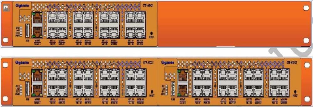
Decide whether you want to front-mount or center-mount the chassis and whether you want to mount single tap or two taps together. Refer Rack Ears for Front Mount , to center-mount reverse the Rack ears. |
|
Figure 2
|
Rack Ears for Front Mount |
|
2.
|
Make sure you have not installed battery pack in the chassis yet. Gigamon recommends rack-mounting the G-TAP A Series 2 before installing battery pack to make it easier to handle the chassis during installation. |
|
3.
|
Select a suitable location for the rack that will hold the G-TAP A Series 2 chassis. Choose a location that is clean, dust free, and well-ventilated. You will need access to grounded power sources. Avoid areas where heat, electrical wire, and electromagnetic fields are generated. Plan for enough clearance in front of a rack so you can access the ports easily ,approximately 25 inches ( 63.50 cm) and enough clearance in the back of the rack to allow sufficient airflow and installation of the rear components such as power supply and battery. |
|
4.
|
Carefully lift the chassis into the rack and place a screw on each side to hold the chassis. |
|
5.
|
Tighten the screws and add additional screws to secure the node |
The G-TAP A Series 2 comes with one short rack ear, one long rack ear, and one splicer plate. Install single chassis with one short ear and one long ear; and to install two chassis together, first install splicer and then install taps with two short ears.


